


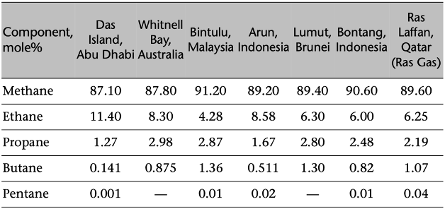
Natural gas is a pivotal energy source that plays a significant role in the global energy landscape. As a cleaner alternative to other fossil fuels, its efficient processing, separation, dehydration, and transportation are crucial to meeting the world's energy demands. This text delves into the intricacies of natural gas processing, advanced technologies for natural gas sweetening, transportation methods such as pipelines and marine CNG, and the liquefaction processes essential for LNG production. The article also covers the emerging field of gas-to-liquids (GTL), highlighting its potential to convert natural gas into valuable liquid fuels, and examines the importance of underground natural gas storage for ensuring a stable supply and managing market fluctuations. Through a comprehensive examination of these topics, this text provides a thorough understanding of the technological advancements and engineering principles that underpin the natural gas industry.
Natural Gas Processing:
A commercially acceptable natural gas should be:
It must be within a specific Btu content range. For example, in the United States, it should be about 1,035 ±50 Btu per standard cubic foot (at 1 atmosphere and 60°F).
It should be delivered at a specified hydrocarbon dew point temperature level. This would prevent liquids to condense and form liquid slugs which could be very damaging to the pipeline
The gas should not contain more than trace amounts of compounds or elements such as hydrogen sulfide, carbon dioxide, mercaptans, nitrogen, water vapor, and oxygen.
The water vapor must be removed (i.e., dehydrate the gas) sufficiently to prevent corrosion and the formation of gas hydrates in the processing plant or the pipelines.
All particulates must be removed.
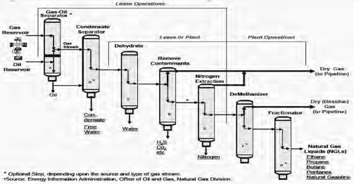
The purpose of gas processing is to produce a gas stream that meets sales requirements and specifications including heating value and the recovery of maximum amount of NGLs (Natural Gas Liquids).
In addition to those four processes (to remove oil, water, compounds, or elements such as sulfur, helium, carbon dioxide, and natural gas liquids), it is often necessary to install scrubbers and heaters at or near the wellhead (EIA, 2006). The scrubbers serve primarily to remove sand and other large particle impurities. The heaters ensure that the temperature of the natural gas does not drop too low to form a hydrate with the water vapor content of the gas stream.
Natural Gas and Liquid Separation:
Gravity separators, centrifugal separators or cyclone separators, filter vane separators, mist eliminator pads, and liquid/gas coalescers are technologies avalilable to achieve this goal
A gravity separator, also called a “knockout drum” or, more formally, gravitational-forces-controlled separator, is typically used as a first-stage scrubber.
Gravity Separation of Two Phases (Gas and Liquid) : In separating two phases (gas and liquid) vertically, gravity and flow direction are expected to play a significant role. The droplets of any liquid in a gas flow are acted on by three forces: gravity (directed downward), buoyancy (opposite of the gravity force), and drag (opposite of the direction of droplet velocity). As a result, the liquid droplet will move in the direction of the net force.
Gravity Separation of Three Phases (Gas, Light and Heavy Liquids) For three-phase separation (Monnery and Svrcek, 1994), while the gas and liquid separation is the same as the one described above, the settling of the heavy liquid droplet in the light liquid is assumed to obey Stoke’s law of buoyancy
Three-phase separator design: Three-phase separators can be either vertical or horizontal, but almost invariably are horizontal.
Natural Gas Dehydration—Water Removal:
Most free water is removed after the gas-liquid separation is at or near the wellhead. However, there are still small amounts of water vapor associated with the main stream of natural gas that requires further treatment to remove (dehydration).
Water Content Determination:
Natural gas, however, is usually a complex mixture and sometimes contains acid/sour gas that changes the behavior of the natural gas, and causes the deviation of water content calculation.
Several methods are available to estimate the water content of sweet and natural gases. One of the most commonly used is the Mcketta and Wehe (1958) approach. They developed a chart to estimate the water content for sweet natural gas. It is clear (from the general chart) that water content or solubility increases, as temperature increases and pressure decreases.
Natural Gas Hydrates: Natural gas hydrates are solid crystalline compounds formed by the chemical combination of natural gas and water under pressure at temperature considerably above the freezing point of water.
Hydrates tend to form when there is:
Free water present and temperature decreases below that of hydrate-formation. This usually happens in the flow string or surface line;
Sudden pressure drop due to expansion. This usually happens when fluids flows through orifices, back pressure regulators, or chokes.
If a small “seed” crystal of hydrate or acid gas (H2S or CO2) is in the system and the flow rate is high with agitation, it will promote the formation of natural gas hydrates.
Adsorbtion Dehydration: It removes water by flowing gas through a granulated solid bed called solid desiccant or adsorbent. Because of the microscopic pores and capillary openings, the solid desiccant has a very large effective surface area per unit weight to retain water on the surface of the solid medium.
Absorption Dehydration: Absorption dehydration is the water removal process by counter-flowing natural gas through a certain liquid solvent that has special attractions or affinities for water. The liquid solvent is called a dehydrating agent or liquid desiccant.
Glycol Dehydration Process
Natural Gas Sweetening—Acid Gases Removal:
The process of removing H2S is called natural gas sweetening.
Iron-sponge sweetening, Alkanolamine Sweetening, Glycol/Amine Process, Sulfinol process, Chemsweet, and Zinc Oxide Process Process are some processes used for natural gas sweetening.
Natural Gas Transportation—Pipelines and Compressed Natural Gas
Pipelines:
Interstate pipelines, often called “trunklines,” are long-distance and wide-diameter (20–42 in.), and traverse more than one state. There are more than 1,400 compressor stations to maintain pressure on this pipeline network. Intrastate pipelines operate inside a single state.
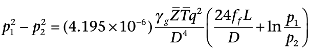
Pipeline design means appropriate size, appropriate distance between compression stations, and adequate compressor sizes that would allow optimum operation and ability to expand in the future. Pipeline throughput depends on pipeline diameter and the operating pressure; taking into account the length of the pipeline and the terrain. Typical onshore pipeline operating pressure is about 700 to 1,100 psi (with some as high 4,000 psi); for offshore pipelines, the operating pressure is typically between 1,400 to 2,100 psi, depending on the material and the age of the pipeline (Speight, 2007).
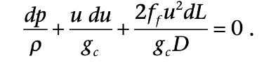
For a horizontal pipeline, the mechanical energy balance is: (Pipeline pressure, dimensions, compression stations can be calculated)
Compression:
The pressure of natural gas flowing through a pipeline decreases along the distance because of friction pressure drop. Therefore, compressors are needed to ensure that the natural gas gets to the destination with sufficient pressure along the path and outlet.
According to the EIA (2007), along the interstate pipeline network, compressor stations are usually placed between 50 and 100 miles apart. Most compressor stations are unmanned, and are monitored by an electronic system that manages and coordinates the operations of several compressor stations. In a large-scale trunckline or a mainline, the average horsepower per compression station is about 14,000, and this can move about 700 MMcf/d of natural gas. Some of the largest stations can handle as much as 4.6 Bcf/day. Two types of compressors are used: reciprocating and turbine engines. Most of them have natural gas-fired and high speed reciprocating engines.
Besides compressors, there are other components in a compressor station. These include scrubbers and filters. Although gas is treated before entering the transportation pipelines, liquid may still condense and accumulate in the pipelines during the transportation process, and particulates may form with the coating materials inside of the pipelines. Thus, liquids and solids have to be removed before entering compressors. Between the parallel or multistage compressors, interstage coolers are needed to cool down the heated gas due to pressurization, further reducing the needed horsepower (hp) of the compressor. The theoretical hp of the compressor required to compress a given amount of natural gas can be obtained from either the analytical solution or an enthalpy-entropy diagram.
Theoretical Horsepower: Horsepower (hp or HP) is the work done over a period of time. One hp equals 33,000 ft-lb/min, or 746 watts, or 75kg-m/s. It is commonly used in measuring the output of piston engines, turbines, electric motors, and other machinery. The theoretical hp of the compressor required to compress a given amount of natural gas can be calculated by assuming the system to be either isothermal (DT = 0) or adiabatic/isentropic (DH = 0). [Of course, in reality, compression of a gas naturally increases its temperature, and there will always be some heat leaking out of the system.]
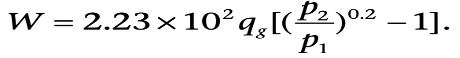
When the system is assumed to be adiabatic, the calculated theoretical hp gives the maximum required hp while under the assumption of isothermal condition; the calculated theoretical value gives the minimum required hp.
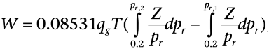
The theoretical work (W in hp) required to compress qg MMscf/d real gas at standard conditions (Tsc = 60°F, psc = 14.65 psia) is given as:
Marine CNG:
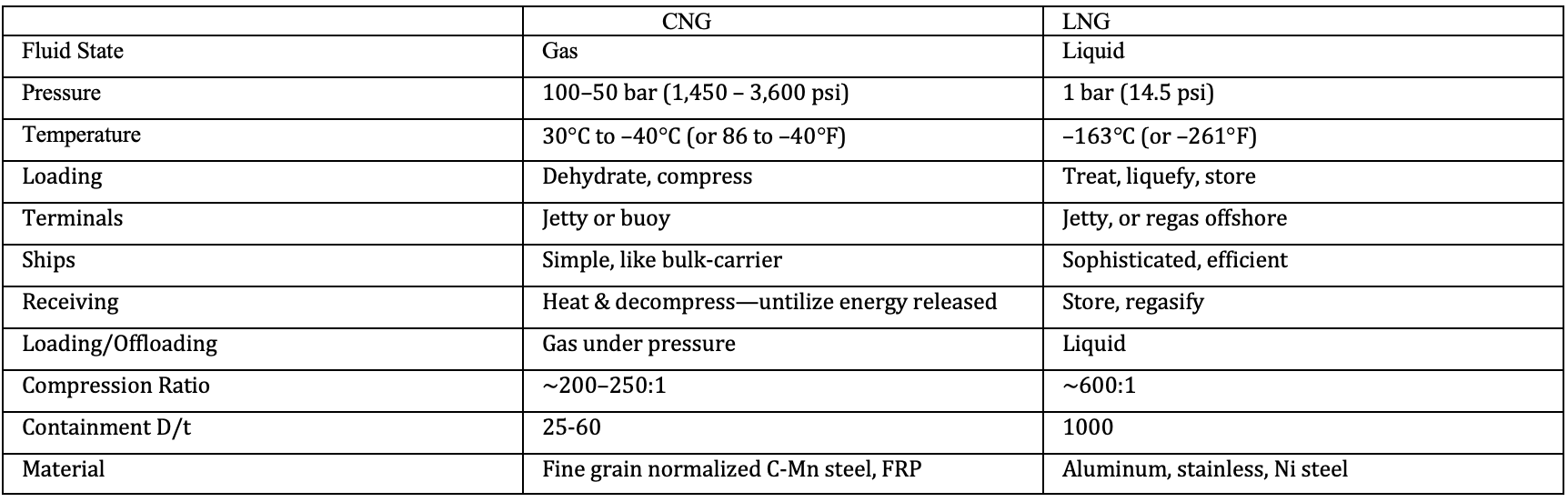
CNG is natural gas compressed at pressures of 2,000 to 3,000 psi (130 to 200 atm) and sometimes chilled (but not liquefied) to temperatures down to –40°F (–40°C) for even higher reduction of its volume. It is a technology proven in many applications, including transport by ship, truck, and barge. It has been used to fuel taxis, private vehicles, and buses worldwide. CNG transportation over sea requires specifically designed CNG ships, which are, in effect “floating pipelines”.
The key differences between these two technologies are summarized in table below
LNG (Liquified Natural Gas)
Liquefied Natural Gas (LNG) has emerged as a critical component in the global energy market, offering a versatile and efficient means of transporting natural gas across vast distances. The process of liquefying natural gas involves cooling it to -162°C (-260°F), at which point it becomes a liquid, reducing its volume by approximately 600 times and making it more feasible for storage and transportation. This transformation is essential for regions that are not connected by pipelines, enabling access to cleaner energy sources and promoting energy security.
The technical aspects of LNG production encompass several sophisticated processes. Pre-treatment stages remove impurities such as water, carbon dioxide, hydrogen sulfide, and mercury, which could freeze or become corrosive at cryogenic temperatures. The purified gas is then cooled using a series of heat exchangers and refrigeration cycles until it reaches its liquefaction point. The liquefied gas is stored in specialized insulated tanks designed to maintain low temperatures and minimize evaporation losses.
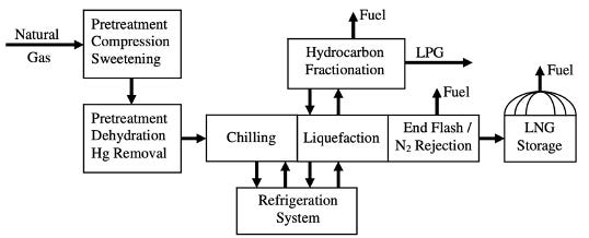
LNG Liquefaction:
The liquefaction process is the key element of the LNG plant. Liquefaction is based on a refrigeration cycle, where a refrigerant by means of successive expansion and compression, transports heat from the process side to where the natural gas is. LNG plants often consist of a number of parallel units, called trains, which treat and liquefy natural gas and then send the LNG to several storage tanks. The capacity of a liquefaction train is primarily determined by the liquefaction process, the refrigerant used, the largest available size of the compressor/driver combination that drives the cycle, and the heat exchangers that cool the natural gas (Smaal, 2003).
The liquefaction process typically accounts for almost 45% of the capital cost of the overall LNG plant (Knott, 2001), which in turn accounts for 25% to 35% of total project costs, when including the regasification facility and the dedicated vessels for transport.
Some methods used in the market:
The Propane Precooled Mixed Refrigerant process—developed by Air Products & Chemicals Int. started to dominate the industry from the late 1970s on. This process accounts for a very significant proportion of the world baseload LNG production capacity. Train capacities of up to 4.5 MTPA have been built
Optimized Cascade LNG Process Phillips Petroleum developed the original Cascade LNG process in the 1960s and was constructed first in Alaska.
Single Mixed Refrigerant Loop Process: The large and expensive LNG projects are often based on processes which require multiple refrigeration systems. The PPMR Process requires two sequential refrigeration systems to accomplish the LNG production task.
The Mixed Fluid Cascade Process (MFCP) was developed by Statoil/Linde. The purified natural gas is precooled, liquefied, and subcooled using three separate mixed refrigerant cycles.
LiquefinTM Process: IFP and Axens have developed the LiquefinTM process with the aim of producing LNG cheaper than with any other process, in good condition, reliable, safe, and friendlier to the environment. With this process, very high capacities can be reached with a simple scheme and standard compressors (Martin et al., 2003). It is a two-mixed refrigerant process designed for LNG base load projects of train sizes up to 6 MTPA.
Dual Mixed Refrigerant (DMR) Process Shell developed a Dual Mixed Refrigerant (DMR) process for liquefaction with two separate mixed refrigerant cooling cycles, one for precooling of the gas to approximately –50°C (PMR cycle) and one for final cooling and liquefaction of the gas (MR cycle)
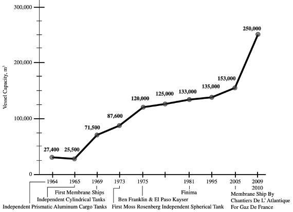
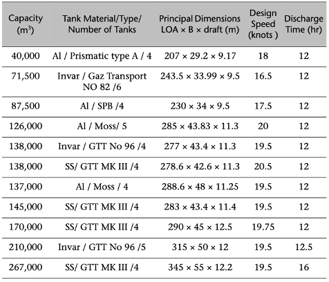
LNG carriers:
Transportation of LNG is primarily conducted via LNG carriers, which are specially designed ships equipped with insulated tanks to keep the LNG in its cryogenic state during transit. Once the LNG reaches its destination, it is regasified at import terminals and fed into the local natural gas distribution network. This supply chain enables countries to diversify their energy sources and reduce dependency on pipeline-delivered natural gas.
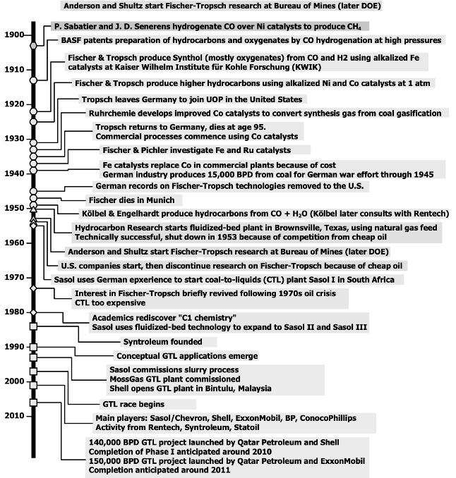
Gas-To-Liquids (GTL)
Gas-to-liquids (GTL) allows the conversion of natural gas into liquid hydrocarbons and oxygenates through chemical reactions. These hydrocarbons are compatible with fuels and chemicals produced in the gasoline and middle distillate range of an oil refinery. They include naphtha, diesel, kerosene, lubricants, and waxes. GTL products may include other chemicals such as ammonia, methanol, or methyl tertbutyl ether (MTBE), a major motor gasoline additive.
While interest in GTL was driven by political (e.g., South Africa during apartheid) rather than economic factors for decades, recent technical advances have made GTL more competitive. In 2009 there were still relatively few facilities in commercial operation (e.g., by Sasol in South Africa and Shell in Malaysia); however, a number of commercial scale facilities were seriously considered, and GTL activity may grow in the future as a result of both private business initiatives and strategic investments by governments of nations with significant natural gas reserves.
Why GTL?
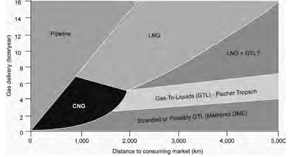
GTL facilitates the transportation of natural gas from remote production sources to consumption destinations if alternative methods, such as pipeline or LNG, are not economically or technically attractive. Since liquid fuels are easier to transport and distribute by ship, rail, or car, and to store at the destination, natural gas conversion to GTL offers superior flexibility in comparison to pipeline and LNG. GTL is not an alternative for places where CNG is attractive because the capital investment for GTL and the operating costs would not be suitable for the size of resources that would fit CNG applications.
A number of additional benefits, all subject to both local and international economics, may result from the use of GTL technologies.
Stranded natural gas monetization from large but difficult places
Exploitation of associated gas
Synthesis of environmentally friendly fuels. The main products of GTL are fuels, such as diesel, and because of the way these fuels are produced they can offer higher performance and lower pollution.
Life extension of pipelines
GTL Processes:
The conversion of pipeline quality natural gas (essentially methane) to liquids is a polymerization process. Hydrogen is removed and methane molecules are polymerized to longer chain hydrocarbon or related molecules, similar to molecules found in crude oil fractions. Such fractions include diesel fuel, naphtha, wax, and other liquid petroleum or specialty products.
There are two basic GTL technologies:
Direct conversion of natural gas to liquid fuels
Indirect conversion via synthesis gas (syngas).
There are two basic GTL technologies: direct conversion of natural gas to liquid fuels and indirect conversion via synthesis gas (syngas). The direct conversion avoids the production of synthesis gas but is difficult to control, has low selectivity (<20%), and low conversion (<40%). Several direct conversion processes have been developed, but none have been economically viable so far.
GTL Based on Direct Conversion of Natural Gas:
Direct conversion of methane to higher hydrocarbons may result from several reactions:
Dehydrogenative self-interaction:
2CH4 —> C2H6 + H2, DG°(500oC) = +35.6 kJ/mol.
Oxidative coupling:
2CH4 + O2 —>C2H4 + 2H2O, ∆G°(500oC) = –374.2 kJ/mol.
2CH4 + 0.5O2 —> C2H6 + H2O, ∆G°(500oC) = –169.3 kJ/mol.
Partial oxidation:
CH4 + 0.5O2—> CH3OH, ∆G°(500oC) = –86.1 kJ/mol.
CH4 + 0.5O2 —> CH2O + H2, ∆G°(500oC) = –83.7 kJ/mol
Oxydehydrochlorination
CH4 + 0.5O2 + HCl —> CH3Cl + H2O, DG°(500oC) = –119.9 kJ/mol.
Complete oxidation
CH4 + 2O2 —> CO2 + 2H2O, DG°(500oC) = –792.9 kJ/mol.
GTL Based on Indirect Conversion of Natural Gas
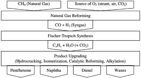
The indirect conversion of natural gas to liquid fuels goes through two main steps (reforming and Fischer-Tropsch) and may be followed by a third step (upgrading).
The first step is natural gas reforming. The main reaction in the reforming step can be loosely described as
CH4 + oxygen source —> CO + H2
where the oxygen source can be steam, CO2, or air. Depending on the source of oxygen, different technologies have been developed, and are discussed below. The product resulting from reforming is composed predominantly of CO and H2. It is called synthesis gas (syngas) because it is used to synthesize products without the need for additional reactants.
The next step is Fischer-Tropsch synthesis. The main reactions in this step can be summarized as
aCO + bH2 —> {CxHy} + {H2O and/or CO2},
where {CxHy} refers to a mixture of liquid straight-chain hydrocarbons that include alkanes (paraffins) and alkenes (olefins) with x ranging from 1 to more than 40, depending on process conditions, catalyst, and syngas composition (ratio a:b). These hydrocarbons result from polymerization of =CH2 groups. The ratio a:b determines whether H2O (hydrogen in excess) or CO2 will be formed.
The final step is product upgrading and usually involves operations such as hydrocracking, isomerization, catalytic reforming, or alkylation. Standard refinery technology can be used in this step. For example, waxes (C18+) are converted into naphtha (C5–C11) and diesel (C12–C18) in a hydrocracker.
Of the above steps, the generation of synthesis gas is the most capital-intensive, accounting for more than half of the fixed cost of an entire GTL process. However, the performance of Fischer-Tropsch synthesis is the most critical for the overall performance of GTL, because it is in this step that the composition of GTL liquids is determined. Critical for Fischer-Tropsch synthesis is the development of catalysts that selectively accelerate reactions resulting in desirable products, as well as the design of corresponding reactors.
Underground Natural Gas Storage
In the United States and a few other countries, the underground storage of natural gas has become increasingly important after World War II. The obvious reason for storage is that, traditionally, natural gas usage has been changing with seasons. The demand has been higher in the winter, prompted by residential heating. Thus, the “base load” and the “peak load” natural gas, not just in different seasons, but also different days within a season, can be quite different. This situation could create an imbalance between the receipts and deliveries of a pipeline network. To avoid supply disruptions, underground storage can be used to provide pipelines, local distribution companies, producers, and pipeline shippers with an inventory management tool, seasonal supply backup, and access to natural gas as needed. In addition, natural gas storage is also used by industry participants for commercial purposes: to store gas when gas price is low and withdraw and sell gas when the price is high.
Types of Underground Storage
Depleted oil or gas reservoirs — The advantage of converting a field from production to storage duty is that one can use the existing wells, gathering systems, and pipeline connections.
Aquifers — An aquifer is suitable for gas storage if the water bearing sedimentary rock formation is overlain with an impermeable cap rock.
Salt caverns—Salt caverns provide very high withdrawal and injection rates relative to their working gas capacity. Base gas requirements are relatively low.
Storage Measures:
Total gas storage capacity is the maximum volume of gas that can be stored in an underground storage facility by design. It is determined by the physical characteristics of the reservoir and installed equipment.
Total gas volume in storage is the volume of storage in the underground facility at a particular time.
Base gas or cushion gas is the volume of gas intended as permanent inventory in a storage reservoir to maintain adequate pressure and deliverability rates throughout the withdrawal season. It contains two elements (Tureyen et al., 2000):
Recoverable base gas is the portion of the gas that can be withdrawn with current technology, but it is left in the reservoir to maintain the pressure.
A non-recoverable base gas is the portion of the gas that can not be withdrawn with the existing facilities both technically and economically.
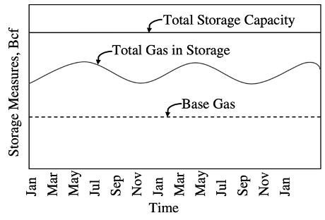
Working gas capacity—the total gas storage capacity minus base gas, i.e., the volume of gas in the reservoir above the level of base gas.
Injection volume—the volume of gas injected into storage fields during a given period.
Deliverability or deliverability rate, withdrawal rate, withdrawal capacity—a measure of the amount of gas that can be delivered or withdrawn from a storage facility on a daily basis with the unit of MMscf/d, same as that for production rate. Occasionally, it is expressed in terms of the equivalent heat content of the gas withdrawn from the facility such as dekatherms per day. A therm is roughly equivalent to 100 SCF of natural gas; a dekatherm is about 1 Mscf. In general, a facility's deliverability rate varies directly with the total amount of gas in the reservoir; it is at its highest when the reservoir is almost full and declines as working gas is withdrawn.
Injection capacity or rate—the amount of gas that can be injected into a storage facility on a daily basis. As with deliverability, injection capacity is usually expressed in MMscf per day, although dekatherms per day are also used. By contrast, the injection rate varies inversely with the total amount of gas in storage; it is at its lowest when the reservoir is almost full and increases as working gas is withdrawn.
Total Gas Volume and Injected Gas Volume in Storage:
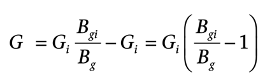
The injected gas volume in a depleted gas reservoir can be calculated by using a similar approach as the “Gas Formation Volume Factor” for the initial gas-in-place calculation of a producing field. Assume the reservoir pore volume is constant, the initial gas-in-place in the depleted gas reservoir in standard conditions is Gi, and the total gas volume in the storage facility is G, then the cumulative injected gas volume, G_s is
G_s =G-G_i
or, by employing the formation volume factors at initial and final conditions
Losses in Gas Storage:
Gas loss in gas storage is a very serious issue. It happens when the cap rock does not seal well, the cement around the wellbore is flawed, or there is communication between the storage and other reservoirs. Once gas loss is happening, the storage deliverability or withdrawal rate will decline from year to year, and the operator will have to bear high costs or even the risk of not meeting the peak demand
For gas storage that is converted from depleted gas reservoir with no water drive, the gas flows to the wells primarily by gas expansion.
There are several ways to determine the reservoir pressure.
One way is to conduct regular (e.g., semiannual) pressure build-up tests similar to pressure surveys done in gas production fields.
Another way is to monitor the bottomhole pressure in observation wells. Ordinarily, these pressure surveys are conducted in the fall and spring when reservoir pressure is near maximum and minimum for total gas volume calculation “Total Gas Volume and Injected Gas Volume in Storage”). The preferred observation well is the one at the location with the highest permeability.
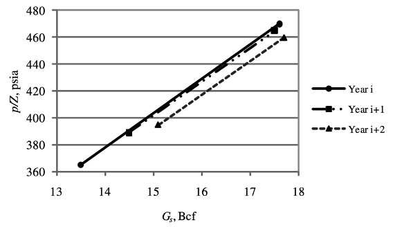
The total gas in storage or gas-in-place can be plotted along with the determined p/Z. If there is no gas loss, all data points should fall on the same line after repeated cycles of injection and withdrawal. If the slope of the line becomes smaller, this is likely to mean that the storage increases because of gas migration or leakage.
When there is gas loss, parallel lines appear from year to year and are shifted toward a larger gas volume at a given p/Z.
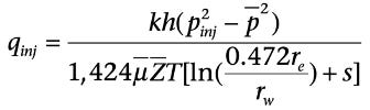
Injectivity in Gas Storage Well:
The expression for injectivity of a gas storage well can be inferred from the expressions for the productivity of a gas well, remembering that in storage, gas is injected into a closed system (unless there is a leak). So steady state is not applicable in injectivity evaluation of gas storage wells. Under pseudo steady state, the injectivity can be calculated by
Natural gas is the cleanest and most hydrogen-rich of all hydrocarbon energy sources, and it has high energy conversion efficiencies for power generation.
Fossil fuels such as oil, natural gas, and coal can be used interchangeably, although with reduced levels of efficiency depending on the use. Coal in the past has been best used for electricity production as it is cheapest, but also the most polluting. New coal plants are likely to incur an additional carbon cost burden through cap-and-trade mechanisms or carbon capture and sequestration (CCS). However, coal can be gasified, at an additional cost, to produce natural gas for lower emissions consumption by various energy end-users. Natural gas can provide space heating at various scales, drive combined-cycle turbines for efficient electricity generation, and, with additional infrastructure costs, provide fuel for road vehicles. It can be reformed from gas to release its hydrogen and to produce longer hydrocarbon liquid fuel molecules through a variety of GTL conversion processes to fuel motor vehicles. Oil can be refined to yield large fractions of gasoline, diesel, aviation fuel, and fuel oil for transportation. Crude oil, distillates, and fuel oil can also be burned directly to produce electricity, or cracked to produce lighter liquids and gases.
Natural gas is the only hydrocarbon source of energy that could easily and at a manageable cost lead to further reductions in global carbon intensity through the reduction in carbon dioxide emissions. Furthermore, natural gas could provide an ultimate bridge to carbon-free energy sources, particularly in the form of hydrogen extracted from the vast available natural gas and methane hydrate (clathrates) resources.